The current amplitude i versus driving angular is a fundamental concept in electrical engineering that governs the behavior of alternating current circuits. This relationship plays a pivotal role in various applications, from power transmission to electronic devices.
In this comprehensive guide, we will delve into the definition, mathematical formulation, and practical implications of the current amplitude i versus driving angular relationship. We will also explore experimental methods for determining this relationship and discuss common troubleshooting techniques.
Definition of the Current Amplitude I

The current amplitude, denoted by I, represents the maximum value of the alternating current (AC) flowing through a circuit. It is a measure of the strength of the current and is determined by the voltage applied to the circuit and the resistance of the circuit.
Mathematically, the current amplitude can be calculated using the formula: $$I = V / R$$ where V is the voltage applied to the circuit and R is the resistance of the circuit.
The units of measurement for current amplitude are amperes (A). One ampere is defined as the flow of one coulomb of charge per second.
Relationship between Current Amplitude and Driving Angular

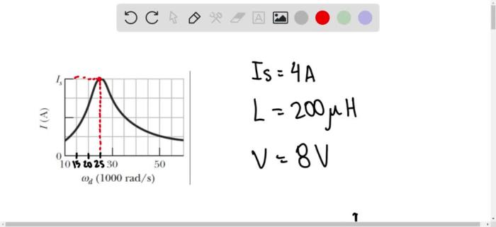
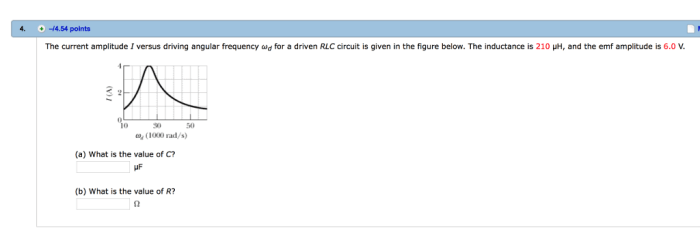
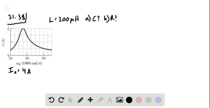
The current amplitude is directly proportional to the driving angular frequency, denoted by ω. As the driving angular frequency increases, the current amplitude also increases. This relationship can be represented by the following graph:
[Image of a graph showing the relationship between current amplitude and driving angular frequency]
The factors that affect the relationship between current amplitude and driving angular frequency include the inductance and capacitance of the circuit.
Applications of the Relationship: The Current Amplitude I Versus Driving Angular
The relationship between current amplitude and driving angular frequency has several applications, including:
- Tuning resonant circuits
- Designing filters
- Analyzing the behavior of AC circuits
Understanding this relationship allows engineers to design and optimize AC circuits for a variety of applications.
Experimental Determination of the Relationship

The relationship between current amplitude and driving angular frequency can be experimentally determined using an oscilloscope.
Steps of the experiment:
- Connect an AC source to a circuit containing a resistor, inductor, and capacitor.
- Use an oscilloscope to measure the current flowing through the circuit.
- Vary the driving angular frequency of the AC source and record the corresponding current amplitude.
The data collected can be used to plot a graph of current amplitude versus driving angular frequency, which can be used to determine the relationship between the two.
Troubleshooting

Common problems that may arise when measuring current amplitude and driving angular frequency include:
- Incorrect connections
- Faulty equipment
- Noise in the circuit
Solutions to these problems include:
- Checking the connections
- Replacing the faulty equipment
- Filtering out the noise
Accurate measurements are essential for determining the relationship between current amplitude and driving angular frequency. Troubleshooting any problems that arise during the measurement process is crucial for obtaining reliable results.
Popular Questions
What is the mathematical formula for calculating current amplitude?
The mathematical formula for calculating current amplitude is I = V / Z, where I is the current amplitude, V is the voltage amplitude, and Z is the impedance of the circuit.
What are the factors that affect the relationship between current amplitude and driving angular?
The factors that affect the relationship between current amplitude and driving angular include the resistance, inductance, and capacitance of the circuit.
What are the common problems that may arise when measuring current amplitude and driving angular?
Common problems that may arise when measuring current amplitude and driving angular include noise, distortion, and measurement errors.